Shop All Categories
Trending products
Specifications:
Pinout:
| PIN | Raspberry Pi Interface (BCM) | Description |
| KEY1 | P21 | KEY1GPIO |
| KEY2 | P20 | KEY2GPIO |
| KEY3 | P16 | KEY3GPIO |
| Joystick UP | P6 | Upward direction of the Joystick |
| Joystick Down | P19 | Downward direction of the Joystick |
| Joystick Left | P5 | Left direction of the Joystick |
| Joystick Right | P26 | Right direction of the Joystick |
| Joystick Press | P13 | Press the Joystick |
| SCLK | P11/SCLK | SPI clock pin |
| MOSI | P10/MOS | SPI data pin |
| CS | P8/CE0 | Chip selection |
| DC | P25 | Data/Command control |
| RST | P27 | Reset |
| BL | P24 | Backlight |
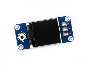
LCD and the controller:
The ST7735S is a 132*162 pixel LCD controller, but the pixel of the 1.44-inch LCD HAT is 128*128. So we have made some processing on the display: the horizontal direction starts from the second pixel to guarantee the location of RAM in the LCD is consistent with the actual location at the same time.
This LCD accepts 8-bits/9-bits/16-bits/18-bit parallel interfaces, which are RGB444, RGB565, and RGB666. The color format used in demo codes is RGB565.
This LCD uses a 4-wire SPI interface for reducing GPIO, and the communication speed will be faster.
Working Protocol:
Different from the traditional SPI protocol, the data line from the slave to the master is hidden since the device only has a display requirement.
RESX Is the reset pin, it should be low when powering the module and be higher at other times.
CSX is slave chip select, when CS is low, the chip is enabled.
D/CX is data/command control pin, when DC = 0, write command, when DC = 1, write data
SDA is the data pin for transmitting RGB data, it works as the MOSI pin of the SPI interface;
SCL works the SCLK pins of the SPI interface.
SPI communication has data transfer timing, which is combined by CPHA and CPOL.
CPOL determines the level of the serial synchronous clock at an idle state. When CPOL = 0, the level is Low. However, CPOL has little effect on the transmission.
CPHA determines whether data is collected at the first clock edge or at the second clock edge of the serial synchronous clock; when CPHL = 0, data is collected at the first clock edge.
There are 4 SPI communication modes. SPI0 is commonly used, in which CPHL = 0, CPOL = 0.
Default Title
Robot Pi Shop
Pickup currently unavailable
Ground Floor Shop, Sayde Street, Fanar Matn 1202
Fanar
Lebanon


RP-000079-WVS
| Price |
|---|
| SKU |
| Rating |
| Discount |
| Vendor |
| Tags |
| Weight |
| Stock |
| Short Description |
Description here
Description here

