- Menu
- Shop All Categories

Trending products


Shop All Categories
Trending products
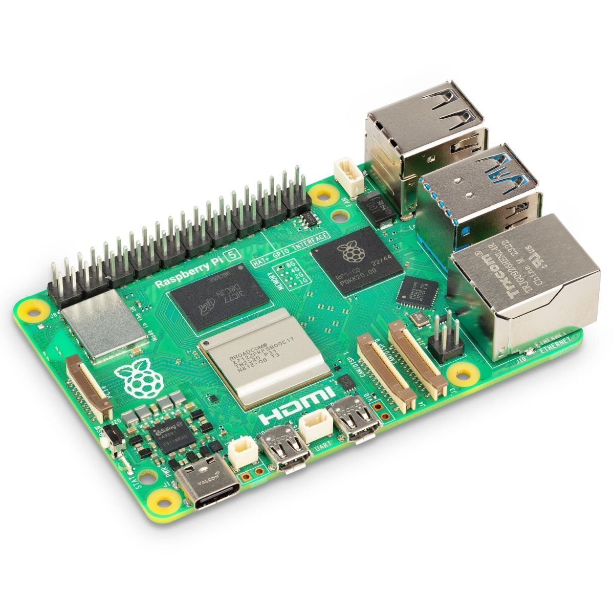
Raspberry Pi
Features:
Specifications:
Onboard Interface
| Function PIN | Raspberry Pi (BCM) | Description |
| 3V3 | 3V3 | 3.3V Power Input |
| GND | GND | Ground |
| SCK | SCK | SPI Clock Input |
| MOSI | MOSI | SPI Data Input |
| MISO | MISO | SPI Data Output |
| CS | CE0 | Data/Command Selection |
| INT | 25 | Interrupt Output |
| Function PIN | Raspberry Pi (BCM) | Description |
| 3V3 | 3V3 | 3.3V Power Input |
| GND | GND | Ground |
| RXD | RXD | UART Receives |
| TXD | TXD | UART Transmits |
| RSE | 4 | Tx/Rx Control |
For the RSE pin, you can choose not to use it, the module factory defaults to use the hardware automatic receive and transmit.
Hardware Description
CAN Bus
The functionality of the CAN module involves handling all message reception and transmission on the CAN bus. When sending a message, it is first loaded into the appropriate message buffer and control registers. Sending operations can be initiated by setting the corresponding bits in the control registers via the SPI interface or by using the transmit enable pin. Communication status and errors can be checked by reading the respective registers.
Any messages detected on the CAN bus undergo error checking, and then are matched with user-defined filters to determine whether the message should be moved to one of the two receive buffers.
As the Raspberry Pi itself does not support the CAN bus, we can use the CAN controller with the SPI interface, along with a transceiver, to realize CAN functionality.
Microchip's MCP2515 is a CAN protocol controller that fully supports the CAN V2.0B technical specification. The device can send and receive both standard and extended data frames as well as remote frames. With two acceptance mask registers and six acceptance filter registers built in, the MCP2515 can filter out unwanted messages, reducing the overhead on the main microcontroller (MCU). The MCU connects to the device via the SPI interface, that is, the Raspberry PI connects to the chip through the SPI interface. For Raspberry Pi, using this chip does not require writing drivers; instead, simply enabling the kernel driver in the device tree is sufficient for usage.
For more details, you can refer to the user manual.
SN65HVD230 is a 3.3V CAN transceiver manufactured by Texas Instruments. This device is suitable for serial communication on CAN buses with higher communication speeds, good noise immunity, and high reliability. SN65HVD230 offers three different operating modes: high-speed, slope and standby. The mode control can be achieved through the Rs control pin. The output pin Tx of the CAN controller is connected to the data input pin D of SN65HVD230, enabling the transmission of data from this CAN node to the CAN network. Similarly, the receive pin Rx of the CAN controller is connected to the data output pin R of SN65HVD230 for receiving data.06.png)
RS485 Bus
The SP3485 interface chip is an RS-485 driver chip used for low-power transceiver communication on RS-485 networks. It operates on a single +3.3V power supply and employs half-duplex communication. The RO and DI pins serve as the output of the receiver and the input of the driver, respectively. The ̅(RE) and DE pins act as the enable pins for receive and transmit operations; the device is in receive mode when ̅(RE) is logic low, and in transmit mode when DE is logic high. The A and B pins are the differential signal lines for receive and transmit operations. When A-B > +0.2V, RO outputs logic 1; when A-B < -0.2V, RO outputs logic 0. Matching resistors, typically 100Ω, are placed between the A and B pins.0006.png)
Among them, the RE and DE pins of the SP3485 chip are set to receive and transmit;
The default factory setting of this module is to use hardware automatic sending and receiving, or you can choose to control the pins on the software to choose to send and receive, you can choose the control method by soldering the 0-ohm resistor on the board.
Hardware automatic control:07.png)
Data Rx: When P_TX is high, it's in an idle state. At this point, the transistor conducts, and the RE pin of the SP3485 chip is at a low level, enabling data reception. RO begins to receive data and forwards the data received at the 485AB port to the MCU.
Data Tx: When P_TX is pulled low, indicating the start of data transmission, the transistor is cut off, and the DE pin is set to a high level, enabling data transmission. At this point, if the data being transmitted is '1', the transistor will be conducting. Although reception becomes valid, the chip remains in a high-impedance state during the transmission phase, so it continues to maintain the transmission state, allowing for the normal transmission of '1'.
Note: the use of an automatic transceiver due to the on-off speed of the transistor, will lead to the automatic transceiver baud rate that can not be too high, if you need a very high baud rate, it is recommended to use the manual transceiver.
Default Title
Robot Pi Shop
Pickup available,usually ready in 1 hour
Ground Floor Shop, Sayde Street, Fanar Matn 1202
Fanar
Lebanon


RP-000087-DVR
| Price |
|---|
| SKU |
| Rating |
| Discount |
| Vendor |
| Tags |
| Weight |
| Stock |
| Short Description |
Description here
Description here